Standard Motors:
Nagpur Motors manufactures standard 3-phase squirrel cage induction motors as per IS 325 and IEC 44. The present range is IEC frame 63 to 180 L in different polarities.
We manufacture standard 3-Phase Squirrel Cage Induction Motors, from IEC frames 63 to 160L are covered in the standard range and covers rating upto 15 Kw in 4 pole and corresponding standard ratings in different polarities. The standard range includes foot mounted (B3) versions as well as flange mounted (B5) and face mounted B14 versions. Special bigger size face mounting as per german (DIN) standards is also available. Technical details of all these are enlisted below.
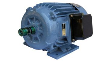
Standard Specification :
- Voltage – 415 Volts +/- 10%
- Frequency – 50 Hz +/- 5%
- Insulation Class – ‘F’ (Temperature Rise limited to class ‘B’)
- Ambient Temp. – 45 Degree C.
- Altitude – 1000 Mtrs
- Protection – IP 44 (Terminal Box IP 54)
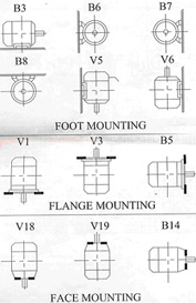
- Mountings – B3-Foot, B5-Flange, B14-Face
Features :
- Available in various frame sizes ranging from 63 to 160L.
- Motors in 63 to 90L Frames are with aluminium Body. With T Box on Top.
- Motors above 90L are with C.I. Body with T Box on side.
- Close grained iron motor housing and end covers.
- Right/Left hand terminal box position
- Shielded bearings for high Dynamic capacity.
- Standard rating and frame sizes available with attached table.
- Standard mounting facilities available as per IS 1231 and IS 2253.
- Motors are in IEC frame sizes with fixing dimensions provided by IS 1231/IS 2223 for foot and flange mounted motors respectively.
Construction Features:
Motors in frame sizes 90 to 180 L have for close-grained grey cast iron motor housings and end covers. Frame 90 motors can be supplied with Alluminium motor housings on request. Motors in frame 71 and 80 are supplied with Pressure Die Cast Alluminium housings as a standard feature. However, motors in these two frames can also be supplied with Cast Iron housings on request. Motors in frame 63 are available with Pressure Die Cast motor housings as well as end covers.
Terminal Box Position:
Motors in frame 90 to 160 L have terminal box on right hand side, which can be changed to left hand side by simple reverse assembly. Frame sizes 63, 71, 80 and 90 (with Pressure Die Cast Housings) have terminal box on top. Frame 180 L motors have terminal box on top, which can be changed on request to terminal box on either side.
Bearing Arrangements
Motors up to frame 132 are supplied with shielded bearings of high dynamic capacity without inner bearing cover. Frame 160 and 180 are supplied with open type bearings with separate inner and outer bearing covers.
| HP | KW | FRAME SIZE | |||
| 2 POLE | 4 POLE | 6 POLE | 8 POLE | ||
| 3000 RPM | 1500 RPM | 1000 RPM | 750 RPM | ||
| 0.16 | 0.12 | 63 | 63 | 71 | 71 |
| 0.25 | 0.18 | 63 | 63 | 71 | 80 |
| 0.33 | 0.25 | 63 | 71 | 71 | 80 |
| 0.5 | 0.37 | 71 | 71 | 80 | 90S |
| 0.75 | 0.55 | 71 | 80 | 80 | 90L |
| 1 | 0.75 | 80 | 80 | 80 | 100L |
| 1.5 | 1.1 | 80 | 90S | 90L | 100L |
| 2 | 1.5 | 90S | 90L | 100L | 112M |
| 3 | 2.2 | 90L | 100L | 112M | 132S |
| 4 | 3 | 100L | 100L | 132S | 132M |
| 5 | 3.7 | 100L | 112M | 132S | 160M |
| 7.5 | 5.5 | 132S | 132S | 132M | 160M |
| 10 | 7.5 | 132S | 132M | 160M | 160L |
| 15 | 11 | 160M | 160M | 160M | 180L |
| 20 | 15 | 160M | 160M | 180L | |
| 25 | 18.5 | 160L | 180L | ||
| 30 | 22 | 180M | 180L | ||
Mountings:
Motors can be used in any of the standard mountings as shown in figure attached as per IS 1231 and IS 2253.
Foot cum Flange mounted or Foot cum Face mounted motors can also be supplied
Dimensions
Motors are in IEC frame sizes and the fixing dimensions conform to IS 1231 for foot mounted motors and IS 2223 for flange mounted motors. The overall dimensions of motors are given in Tables attached.
Foot Mounting

| FEAME | FIG | A | AB | AC | AD | B | BB | C | D | E | F | GA | GD | GE | H | HA | HC | HD | K | L |
| 63 | B | 100 | 119 | 116 | 58 | 80 | 97 | 40 | 11 | 23 | 4 | 12.5 | 4 | 2.5 | 63 | 8 | 120 | 152 | 7 | 210 |
| 71 | A | 112 | 130 | 114 | 90 | 110 | 45 | 14 | 30 | 5 | 16 | 5 | 3 | 71 | 8 | 143 | 7 | 225 | ||
| 71 | B | 112 | 132 | 134 | 67 | 90 | 115 | 45 | 14 | 30 | 5 | 16 | 5 | 3 | 71 | 10 | 139 | 172 | 7 | 255 |
| 80 | A | 125 | 150 | 164 | 100 | 122 | 50 | 19 | 40 | 6 | 21.5 | 6 | 3.5 | 80 | 8.5 | 162 | 10 | 295 | ||
| 80 | A | 125 | 152 | 156 | 78 | 100 | 125 | 50 | 19 | 40 | 6 | 21.5 | 6 | 3.5 | 80 | 12 | 159 | 179 | 10 | 295 |
| 90S | B | 140 | 172 | 184 | 160 | 100 | 131 | 56 | 24 | 50 | 8 | 27 | 7 | 4 | 90 | 10 | 182 | 10 | 330 | |
| 90L | A | 140 | 172 | 184 | 160 | 125 | 156 | 56 | 24 | 50 | 8 | 27 | 7 | 4 | 90 | 10 | 182 | 10 | 330 | |
| 100L | A | 160 | 192 | 208 | 175 | 140 | 180 | 63 | 28 | 60 | 8 | 31 | 7 | 4 | 100 | 12 | 204 | 257 | 12 | 390 |
| 112M | A | 190 | 226 | 232 | 185 | 140 | 180 | 70 | 28 | 60 | 8 | 31 | 7 | 4 | 112 | 12 | 228 | 281 | 12 | 390 |
| 132S | A | 216 | 256 | 270 | 205 | 140 | 180 | 89 | 38 | 80 | 10 | 41 | 8 | 5 | 132 | 13 | 267 | 320 | 12 | 470 |
| 132M | A | 216 | 256 | 270 | 205 | 178 | 218 | 89 | 38 | 80 | 10 | 41 | 8 | 5 | 132 | 13 | 267 | 320 | 12 | 500 |
| 160M | A | 254 | 320 | 328 | 275 | 210 | 310 | 108 | 42 | 110 | 12 | 45 | 8 | 5 | 160 | 23 | 324 | 394 | 15 | 660 |
| 160L | A | 254 | 320 | 328 | 275 | 254 | 310 | 108 | 42 | 110 | 12 | 45 | 8 | 5 | 160 | 23 | 324 | 394 | 15 | 660 |
| 180M | A | 280 | 370 | 370 | 242 | 320 | 121 | 48 | 110 | 14 | 51.5 | 9 | 5.5 | 180 | 25 | 335 | 440 | 15 | 740 | |
| 180L | A | 280 | 370 | 370 | 242 | 320 | 121 | 48 | 110 | 14 | 51.5 | 9 | 5.5 | 180 | 25 | 335 | 440 | 15 | 740 |
Flange Mounting
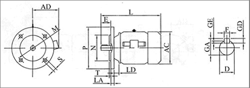
| FEAME | AC | AD | D | E | F | GA | GD | GE | L | M | N | P | LA | LD | S | T |
| 63 | 116 | 58 | 11 | 23 | 4 | 12.5 | 4 | 2.5 | 210 | 115 | 95 | 140 | 9 | 16 | 10 | 3 |
| 71 | 144 | 114 | 14 | 30 | 5 | 16 | 5 | 3 | 265 | 130 | 110 | 160 | 9 | 18.5 | 10 | 3.5 |
| 80 | 164 | 134 | 19 | 40 | 6 | 21.5 | 6 | 3.5 | 310 | 165 | 130 | 200 | 10 | 20.5 | 12 | 3.5 |
| 90 | 184 | 160 | 24 | 50 | 8 | 27 | 7 | 4 | 330 | 165 | 130 | 200 | 10 | 21 | 12 | 3.5 |
| 100 | 208 | 175 | 28 | 60 | 8 | 31 | 7 | 4 | 400 | 215 | 180 | 250 | 11 | 25 | 15 | 4 |
| 112 | 232 | 185 | 28 | 60 | 8 | 31 | 7 | 4 | 400 | 215 | 180 | 250 | 11 | 25 | 15 | 4 |
| 132 | 270 | 205 | 38 | 80 | 10 | 41 | 8 | 5 | 500 | 265 | 230 | 300 | 12 | 26 | 15 | 4 |
| 160 | 328 | 275 | 42 | 110 | 12 | 45 | 8 | 5 | 660 | 300 | 250 | 350 | 13 | 34 | 19 | 5 |
| 180 | 370 | 190 | 48 | 110 | 14 | 51.5 | 9 | 5.5 | 740 | 300 | 250 | 350 | 13 | 34 | 19 | 5 |

| FEAME | AC | AD | D | E | F | GA | GD | GE | L | M | N | P | T | S | DEPTH | M | N | P | T | S | DEPTH |
| 63 | 116 | 90 | 11 | 23 | 4 | 12.5 | 4 | 2.5 | 210 | 75 | 95 | 90 | 2.5 | M5 | 6 | 100 | 95 | 120 | 3 | M6 | 10 |
| 71 | 144 | 114 | 14 | 30 | 5 | 16 | 5 | 3 | 265 | 85 | 110 | 105 | 2.5 | M6 | 8 | 115 | 110 | 140 | 3 | M8 | 10 |
| 80 | 164 | 134 | 19 | 40 | 6 | 21.5 | 6 | 3.5 | 310 | 100 | 130 | 120 | 3 | M6 | 8 | 130 | 130 | 160 | 3.5 | M8 | 10 |
| 90 | 184 | 160 | 24 | 50 | 8 | 27 | 7 | 4 | 330 | 115 | 130 | 140 | 3 | M8 | 10 | 130 | 130 | 160 | 3.5 | M10 | 12 |
| 100 | 208 | 175 | 28 | 60 | 8 | 31 | 7 | 4 | 400 | 130 | 180 | 160 | 3.5 | M8 | 10 | 165 | 180 | 200 | 3.5 | M10 | 12 |
| 112 | 232 | 185 | 28 | 60 | 8 | 31 | 7 | 4 | 400 | 130 | 180 | 160 | 3.5 | M8 | 10 | 165 | 180 | 200 | 3.5 | M10 | 12 |
| 132 | 270 | 205 | 38 | 80 | 10 | 41 | 8 | 5 | 500 | 165 | 230 | 200 | 3.5 | M12 | 12 | 165 | 230 | 200 | 3.5 | M12 | 12 |

